The first order of business for the amplifier was figuring out how I was going to amplify the audio signals that go to the speakers. These power amplifiers dominate the power requirements for the entire project, so knowing the technology I was going to use and the requirements were necessary before being able to move forward with a transformer, for example.
I was originally thinking of pulling out my old university textbook on “Transistor Amplifier Design” and taking a stab at designing something using individual components (known as a discrete design in the field). The problem with this approach is that was one of the hardest classes of my university education, and I remember struggling with some of the concepts. I had a lot going on that year, and I think re-reviewing the material would have shed a lot of light on the area. But I was stepping pretty far out my comfort zone with that approach.
Around that time I stumbled upon something called a Gainclone.
The Gainclone
In 1999, a company released a hi-fi audio amplifier called the Gaincard for roughly $3300 USD. It was small and simple, but it received rave reviews. The case was sealed up shut, but eventually someone decided to crack one open and look inside (photo from 6moons.com).
Inside were hardly any components, and at its heart, a relatively cheap power opamp from National Semiconductor called the LM3875. It was estimated that the Gaincard had less than $100 worth of parts in it, but it retailed for $3300.
What was more surprising was just how incredible it sounded. The conventional wisdom at the time was you needed more and more components to get the audio quality to something acceptable. The Gaincard showed people that a simple, well thought-out design could outperform other high-end audio at the time.
Not long after, a few people reversed engineered the design and created the first replicas, affectionately called Gainclones. Similar to the $3300 designs, these sounded incredible, and easily passed into high-fidelity territory.
The LM3886
The successor to the chip used in the The Gaincard, the LM3875, is the National Semiconductor LM3876. That chip allows for up to 68 Watts of power in a single channel at 4 Ohms impedance, and also provides a mute function that didn’t exist on the original.
Since the LM3886 chip has been widely used and researched for the past 20 years, and it required both a minimum amount of knowledge and components to create a single channel, I quickly warmed to the idea of using it in my amplifier. I would need five of them of course, two each for the front and rear left and right channels, and one for the centre. But it seemed doable.
Class AB
The LM3886 amplifier runs in a Class AB configuration. What that means is that the transistor amplifier part of the design is running at some idle current roughly 50% of the time (which means it burns power even when it’s not actively amplifying a signal). The LM3886 datasheet says at idle, with no audio, it will draw roughly 50 milliamps. So if it’s powered by a dual power supply +/- 28V, then the idle power is (28 – -28)*0.50 Amps = 2.8 Watts. And if there are five of them, that brings idle current power up to 14 Watts.
In addition, a Class AB topology isn’t horribly efficient, usually around 60% or so. So that means to product 10 Watts of output power, it might take 16.5 Watts of power. Those extra Watts, the 6.5 Watts in my example, have to be dissipated as heat. Which is why most power amplifier stages for Class AB amplifiers have hefty heat sinking requirements.
This power dissipation changes with the output power that is generated, which is a function of the speaker impedance as well as the power supply voltage. If you increase the power supply voltage, for example from +/-28V to +/-35V, the power dissipation and heat-sinking requirements go up dramatically. Similarly, if you drop the speaker impedance from 8 Ohms down to 6 Ohms, the maximum power capability of the LM3886 increases, but so does the heat generation. Taken all together, the ideal supply voltage (and the one I need to determine before I can source a transformer) is basically a function of the desired output power and the speaker impedance.
My Dali Oberon 3 speakers, my main listening speakers, are 6 Ohm, but I also have a set of Cambridge Acoustics speakers that are 8 Ohms. I’ve never owned a pair of 4 Ohm speakers before, nor do I think I ever will (they are more prevalent in car audio”). So it seemed reasonable to me to split the difference and design something that will work with both 6 Ohm and 8 Ohm speakers, even if it meant sacrificing my ability to use 4 Ohm speakers.
Thankfully there exists an easy-to-use Excel spreadsheet, the Overture Design Guide where a person can play with all the variables and see how it ends up when using any of the National Semiconductor chips.
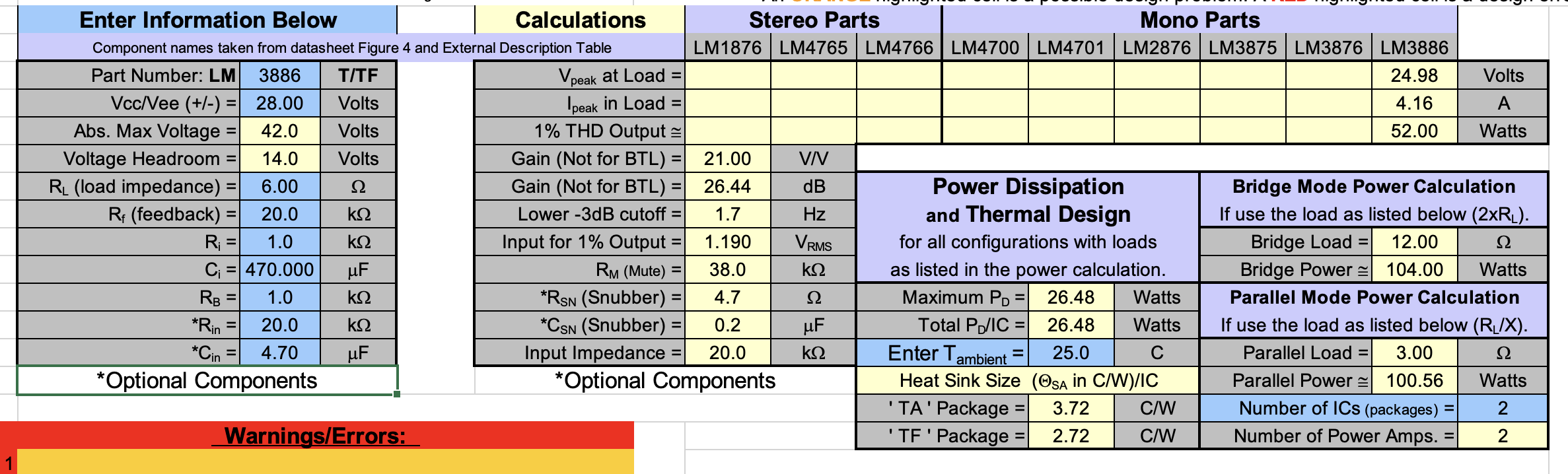
Design Calculations For the LM3886 Power Amplifier
The screenshot above of the Overture Design Guide are the parameters I eventually settled on. Using a DC supply voltage of +/- 28V, running into my Dali Oberon 3 speakers at 6 Ohms, I can expect 52 Watts of output with a THD distortion of 0.1%. That power level easily satisfies my requirement of getting at least 20 – 40 Watts out of my amplifier per channel.
It’s important to also note the heat-sinking requirements listed in the Excel sheet. For that design, I would need a heat-sink of at least 3.7 Celsius / Watt. At 52 Watts of output, the LM3886 needs to dissipate a rather large 26.5 Watts as heat. Using a heat-sink of 3.7 Celsius / Watt and dissipation 26.5 Watts of power means the heatsink will rise 98 Celcius above ambient temperature. In the case of a normal room temperature of about 20 C, the heatsink will be at 118 Celsius – that’s hot, and it would easily burn you if you touched it.
Since the numbers in the spreadsheet don’t represent the ideal heatsink sizes, but rather represent the temperature at which horrible things start happening in the LM3886 (for example, the Spike protection circuity may kick in which severely distorts the audio), it’s apparent we can do a bit better.
If we set an upper limit on the temperature we are willing to accept, then we can determine a more appropriate heatsink – i.e. if we say the heatsink shouldn’t ever get above 65 Celsius (a temperature at which a person could briefly touch without burning themselves), then that means the heatsink needs to only rise 45 Celsius while dissipating 26.5 Watts. A heatsink with that requirement needs to be rated at at least 45 Celsius / 26.5 Watts = 1.7 Celsius / watt.
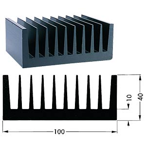
1.5 C/Watt Heatsink
A heatsink that is close to those ratings is shown above. As you can see, at 75x100x40mm in size, that’s a pretty massive heatsink. And that’s just for one channel.
But I think we can relax the requirements a bit more, mainly because I don’t intend to ever listen to music at 52 Watts. While the datasheet doesn’t include any data for 6 Ohm speakers, we can infer a rough data point between the 8 Ohm and 4 Ohm graphs.
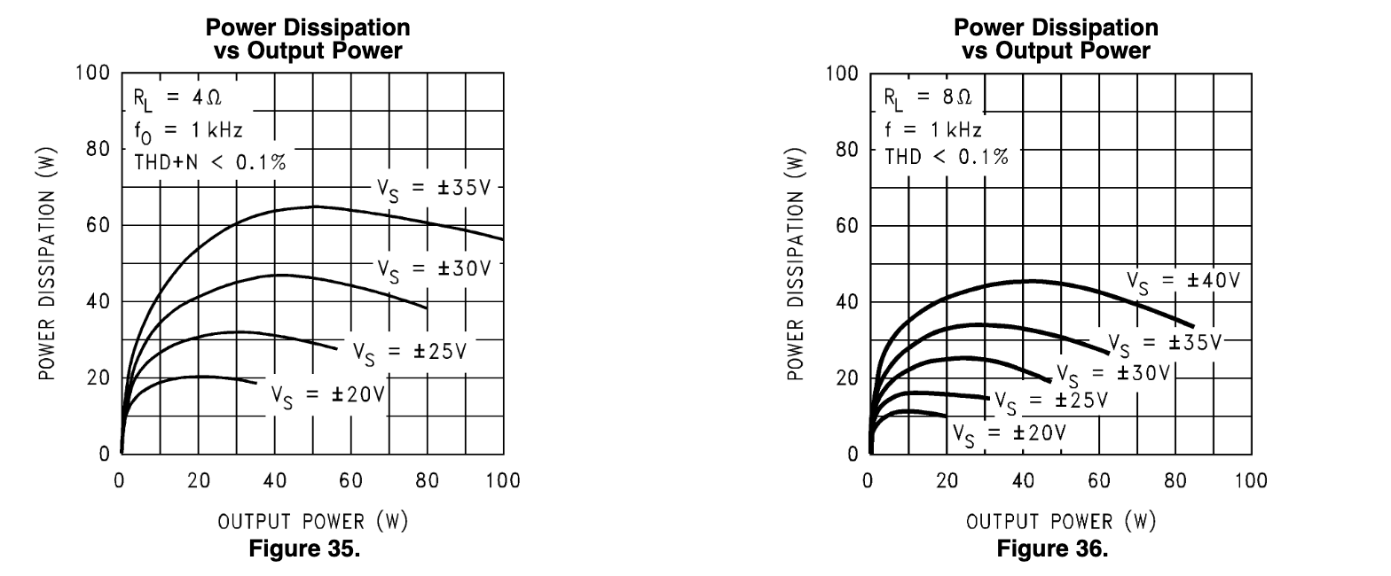
LM3886 Power Dissipation At 4 And 8 Ohms
So at roughly 5 Watts of power output, which is probably a very loud listening level, the LM3886 would dissipate about 20 Watts. Using the same equations above shows that we can use any heatsink less than 2.25 Celcius / Watt and still maintain heatsink temperatures that would be safe to at least momentarily touch.
